|
|
|
|
|
|
|
|
One of the most powerful features of BioTapestry is its hierarchical model. All network elements are defined in the top level View from the Genome (VfG) model (aka the "Full Genome"), then the relevant chunks of this full model can be used in multiple regions in the models at the next View from All Nuclei (VfA) level of the hierarchy. Finally, in the third (fourth, fifth...) View from the Nucleus (VfN) model levels, typically the active and inactive portions of the parent models are shown.
The user is allowed to create their network models at any level of this hierarchy. For example, they can first draw the top-level VfG model, then "push" or "pull" network elements down to different regions in the various lower model levels. Alternately, they can draw new elements at the VfA or VfN levels, and those elements will be automatically included in all the parent models up to the top.
But working with the hierarchy can take some getting used to, particularly when creating networks at the lower VfA and VfN levels. If, for example, a user draws a gene in a VfN and then deletes the gene from the VfN, it still exists in all the parent models. (The user needs to go to the top level VfG model to globally delete a gene, node, or link). Furthermore, although the system restricts the user to have only one copy of a gene of a given name in the top-level VfG, other node types do not have this restriction. So if the user draws a text node in a VfN with the name Ubiq in Region A, and then draws the same text node Ubiq in another Region B, there are two possible cases. They either (1) want to have two different nodes with the same name in the top model, or (2) want to reuse the first node in the top model in two different regions. Similar problem can arise when drawing links. Does the user really want two copies in the top model, or just reuse the single copy in the two different contexts?
BioTapestry detects these cases and asks the user what they want to do, but errors can still creep in. So the resulting VfG can begin to accumulate several undesirable elements:
When viewing the top-level model, you can select Edit->Select Top-Level-Only Elements to bring up the option to select Nodes or Links. Once these are selected, you can mouse shift-click (hold down shift key while clicking with mouse) to remove any elements you wish to keep, and then hit the Delete key to remove those selected items that are not being used anywhere else in the model hierarchy.

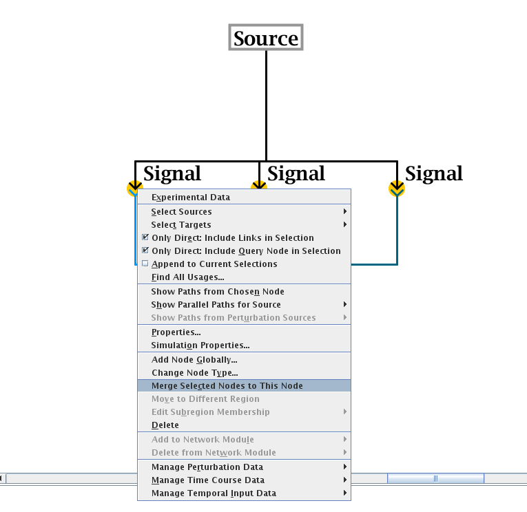
When viewing the top-level model, the user can use mouse shift-click to select all the nodes (of the same type) that need to be merged. Then, right-click on the node that you wish to remain after the operation, and select Merge Selected Nodes to This Node from the pop-up menu (see figure below). If possible, the nodes will be merged into the single node, though if the program detects cases where node merges are inappropriate, it will perform only a partial merge. An example of a partial merge would be if two different nodes of the same type and same name appear in the same region in a submodel. As part of the node merge, any link duplicates that are created after all the links are moved onto the final node will be merged as well.
When the user draws new links in child models between the same source and target in different regions, instead of reusing existing links that are already present in the top model, we end up with unnecessary duplicate links present in the top-level model. Note that this is distinct from the commmon case of having e.g. multiple links from the same source landing on different cis-reg modules of a single target gene; in that case it is appropriate to have multiple links.
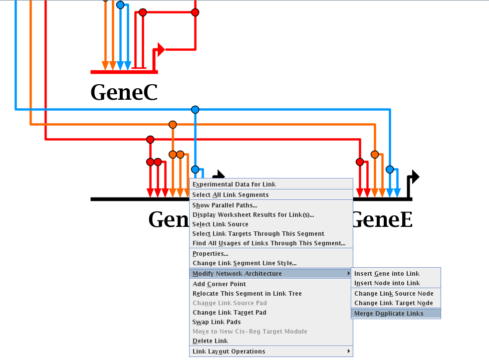
To eliminate duplicate links, go to the top-level model, right-click on a link (typically right above where it lands, so that the link tree segment is unique to one link). From the pop-up menu select Modify Network Architecture->Merge Duplicate Links (see figure below). The program will then merge as many links as possible, while making sure not to merge links of different signs or evidence levels.
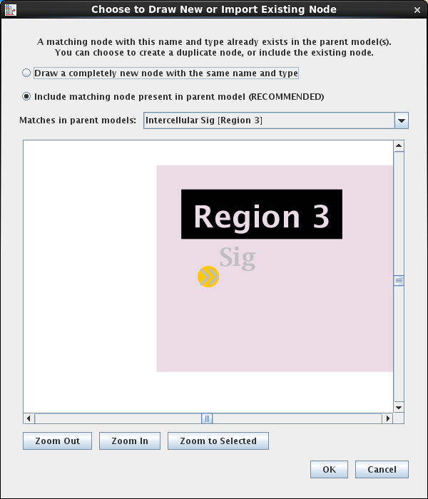
If the user specifies that they wish to draw a new link or node in a submodel, but BioTapestry detects that an existing copy could do the job, the system has always popped up a dialog offering to switch to using the existing element. Unfortunately, the default setting tended to direct users to creating the duplicate, and did not highlight what is probably the preferred option. The dialog text and default settings have been changed in Version 7.1; see below for an example.
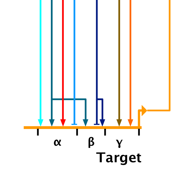
One of BioTapestry's unique features is that the user can specify distinct cis-regulatory regions on a gene, providing a schematic representation of the regulatory architecture:
In previous versions, these modules were simply labels attached to ranges of "landing pads" on the gene. The bounds were set using a table in the gene properties dialog that was not user-friendly. Additionally, one severe drawback was that if the user changed the module bounds in the table, the links would not shift accordingly to retain their module membership, and the user needed to perform a tedious manual clean-up step. Furthermore, when a link landing pad was changed to shift module membership in the parent, the child models were not kept in sync with that shift. The user needed to do these changes manually.
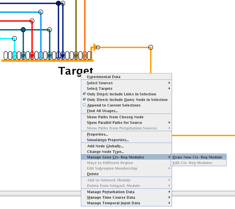
Version 7.1 has significantly improved this feature. First, modules are created by drawing them, and links within the bounds of the new modules now belong to those modules. To draw a module, go to the top-level model, right-click on the gene name, and select Manage Gene Cis-Reg Modules->Draw New Cis-Reg Module from the pop-up menu:
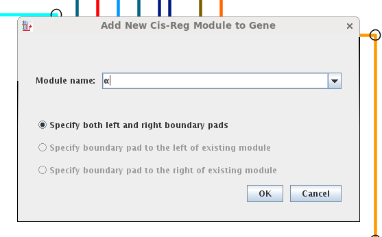
Specify the name of the module (greek letters are provided in the drop-down, or you can provide your own). If modules already exist, you have the option to choose to click on just one landing pad to specify the module. With an empty gene, you must click on two pads:
The link pads will appear on the gene, and you click on the two pads that define the first and last pads of the module (here, the pads with the cyan and sky blue inbound links):
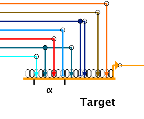
In the above case, the four links contained in the new module are now tied to it (and the other are implicitly not tied to it). For example, if there were other models where the links had been drawn in a different order, creating the module will change the link landing pads in the other models to move member links into the module, and non-member links out of the module.
The user can also edit existing module configurations. To edit the modules, go to the top-level model, right-click on the gene name (not the module names), and select Manage Gene Cis-Reg Modules->Edit Cis-Reg Modules from the pop-up menu:
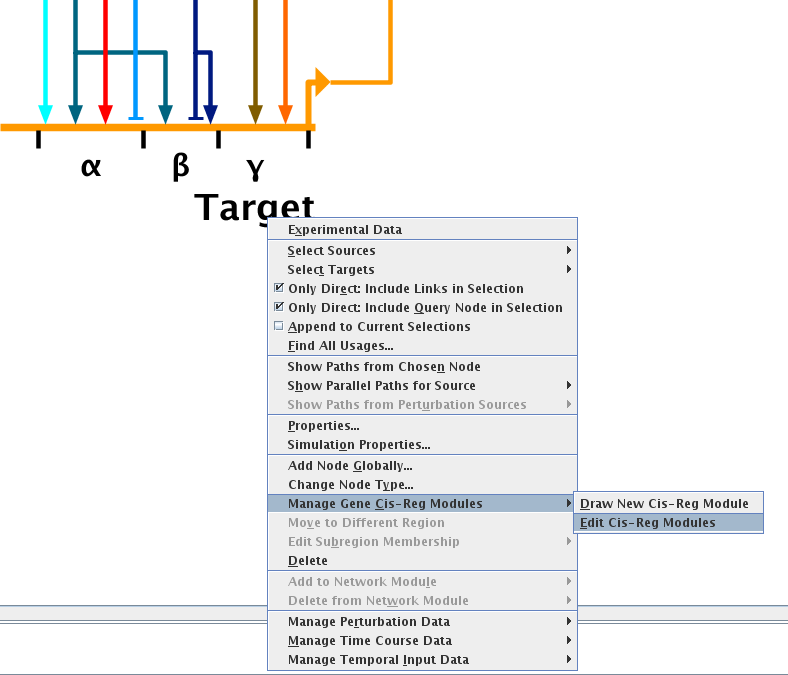
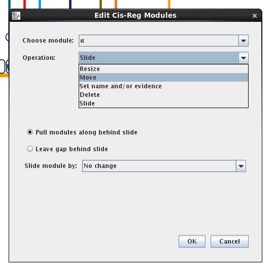
In the dialog that appears, the user can select the module to edit, and then choose to resize it, move it between other modules, rename it, delete it, or slide it along the gene. The other modules will be modified as well according to the options chosen in the dialog. Most critically, the links into the module will track the changes and be shifted accordingly, in all levels of the model hierarchy.
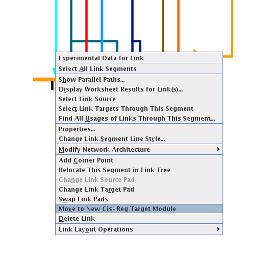
Because of these changes, the Change Link Target Pad and Swap Link Pads commands in links targeting a gene with cis-reg modules are now restricted. They only work to shift link target pads while staying within a cis-reg module. To move links between modules, use the new Move to New Cis-Reg Target Module operation in the link pop-up menu (see below). When the link is shifted, the shift is applied globally to all instances where that link appears.
Finally, since the implementation of cis-reg modules has changed to be more stringent, older models may have inconsistencies that are not compatible with the current approach (e.g. links in child models may not match parent module membership). Older files will be checked when loaded, and fixes will be applied. A dialog will provide details of any changes that were carried out. Users should inspect this listing to make sure they are consistent with what the user wants.
BioTapestry is designed to explicitly show how a network takes on different states in various regions and different times. A key part of this is that it displays elements that are active as colored, and inactive as grayed-out. This inactive gray color is not achieved by explicitly setting the presentation property to gray, but by specifying in the network model that the element is inactive, where the software automatically draws these inactive elements as gray.
One problem is that in earlier versions of the software, it could be time consuming to have to go through each element and set it to inactive. More recently, it became possible to make simultaneous property changes to all selected elements using Edit->Edit Current Selection->Edit Multiple Current Selections... and setting elements to inactive using the provided dialog.
In Version 7.1, this very frequent operation of setting large pieces of the network to inactive has been made more convenient with a new keyboard accelerator. The user just goes to a submodel (the top-level VfG "global parts list" model does not support the concept of inactive elements), selects multiple elements using mouse shift-clicks or rubber-band boxing, and then presses Ctrl-G to set the selected genes, nodes, and links to inactive.
One caveat to keep in mind is that you should work "from the bottom up" in the network heirarchy when inactivating elements. This is because a parent model cannot set a gene, node, or link to inactive while a child model still shows it as active. A child model cannot contain network elements that the parent does not also contain, and an "active" gene with an "inactive" parent is not deemed to meet this rule.
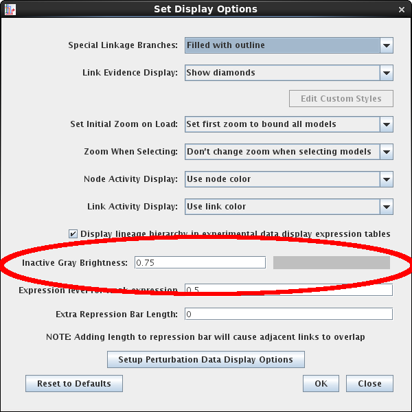
The previous default brightness color for inactive gray was fixed, and that level sometimes made it hard to see the inactive features when BioTapestry models were being displayed using some digital projectors. The value can now be set as one of the configurable display options. Go to Edit->Set Display Options... and set the Inactive Gray Brightness value to between 0.5 and 0.75 (inclusive):
Last updated: September 5, 2023
biotapestry at systemsbiology dot org