|
|
|
|
|
|
|
|
Note: This version of FAQ Answers: Automatic Layout Tools shows reduced-size screen shots. You can click on any image and see the full-size image in a separate window. To get the version with full-size images, go here.
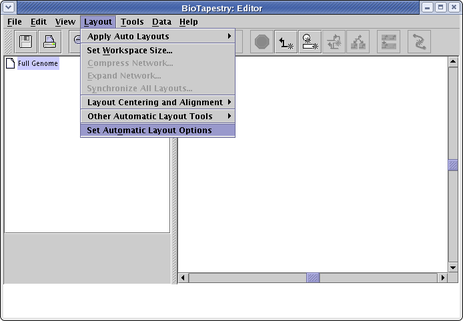
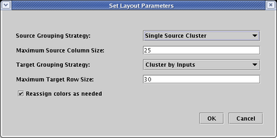
Starting with Version 2, the user can select two different automatic layout methods for top-level networks; you can then use the layout synchronization tool to propagate the top-level network layout down to submodels. You can apply these layouts to any network, both those you draw, as well as those built up from interactions lists. These new layout methods are also used when importing SIF files or CSV files, unless the user requests that the current layout be maintained, in which case the older Version 1 incremental layout algorithm is used to organize any new additions. The automatic layout parameters to use for file imports, as well as the default settings that will appear when you call up the automatic layout tools, are set using the layout options dialog, which you choose by selecting Layout->Set Automatic Layout Options from the main menu:
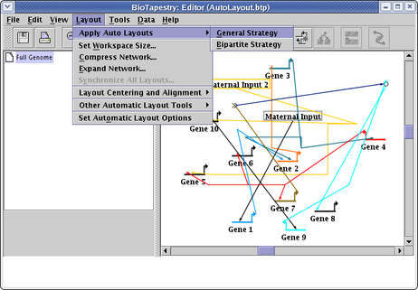
There are two different automatic layout "templates" you can use: General and Bipartite:
The General layout can handle any type of topology. All genes with outputs are grouped on the left, while pure targets are grouped on the right. The criteria for ordering the groups can be set as layout options (e.g. time of first expression, topological sort of the network, common inputs, etc). Ancillary nodes such as bubbles or signals are clustered with the most appropriate source or target gene. To access this feature, select Layout->Apply Auto Layouts->General Strategy:
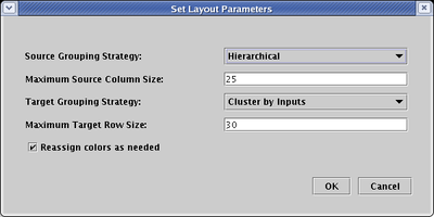
The parameters you set can have profound effects on the final layout, so it is worth playing around with them. For example, if you set the Source Grouping Strategy to Hierarchical:
you will get something like this (following an additional network compression step to remove extra space):
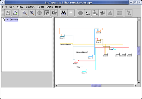
If you instead set the Source Grouping Strategy to Single Source Cluster:
you will get something like this (again following an additional network compression step to remove extra space):
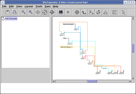
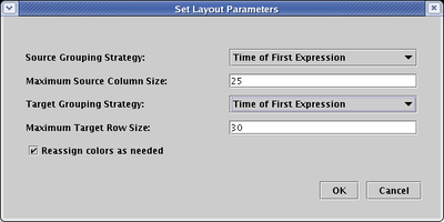
If the nodes have supporting temporal expression data, you get a third Source Grouping Strategy, and you can select Time of First Expression. Note that the Target Grouping Strategy has also been changed to this:
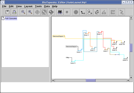
After a round of network compression, and a link optimization pass applied to just the Gene 3 and Gene 7 outputs, you will get something like the following. This example shows how the layout works for much larger sets of source genes: genes that turn on at the same time are grouped in clusters that alternate above and below the main central track of accumulating links that are eventually distributed to the targets on the right hand side.
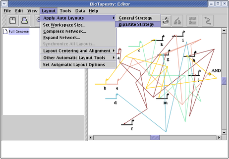
The Bipartite layout works well when genes can be divided into two disjoint groups: sources and targets. In other words, source genes cannot themselves be targets of other source genes. While obviously very specialized, this is very useful for a certain class of data sets. It can handle networks that are not strictly bipartite, in that certain ancillary nodes (bubbles, signals, etc.) that are themselves targets, but which then have outputs which are exclusive to a target gene, will be laid out adjacent to the target gene. To use this layout feature, select Layout->Apply Auto Layouts->Bipartite Strategy from the main menu:
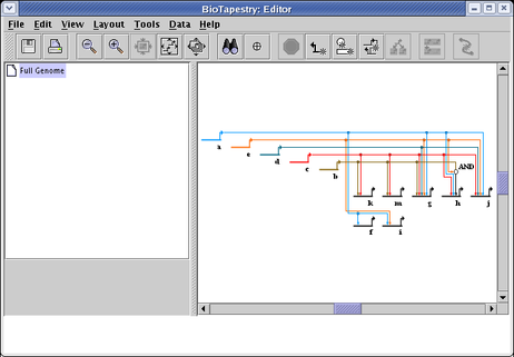
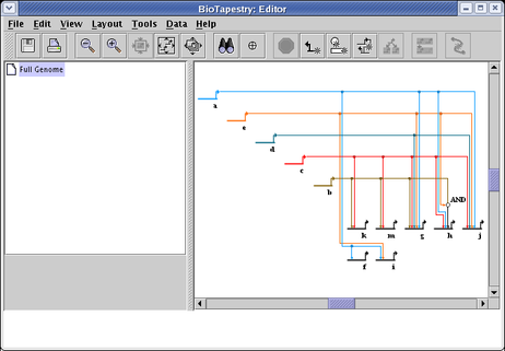
The resulting layout, following a round of network compression, is shown below. Note that the Special Link Branches display option has been set to Filled with Outline, which works very well in combination with this layout to highlight the targets of a given source. Also, note how the AND bubble node has been laid out next to the h. The network is thus not strictly bipartite, but these special cases are handled anyway:
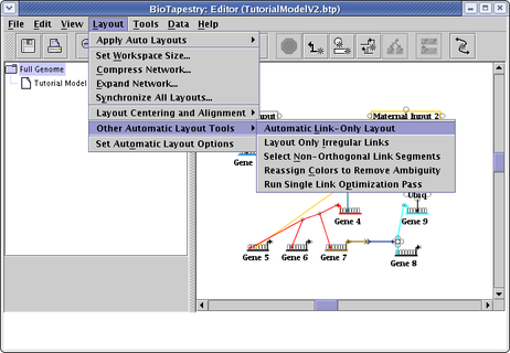
The auto layout tools described above layout everything: genes, nodes, and links. They are a great way to load in networks from files, or to organize and layout a huge network without having to draw them. However, if you want to manually place nodes and genes, but let the program handle placing the links, then the automatic link-only layout tools may be useful. If you want all the links in the network laid out automatically, select Layout->Other Automatic Layout Tools->Automatic Link-Only Layout:
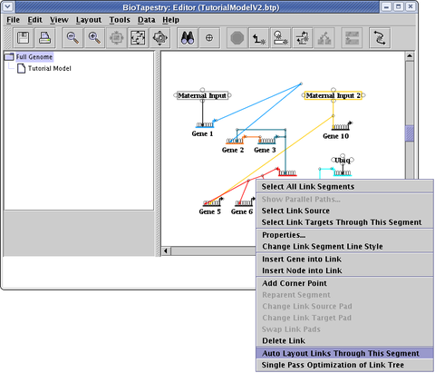
If you have spent time laying out links manually, and you do not want to throw away that effort, but still have lots of links that are crooked and in need of cleanup, a better alternative is to select Layout->Other Automatic Layout Tools->Layout Only Irregular Links (see above; this option is right below the Automatic Link-Only Layout choice). Even more precise control can be obtained by right-clicking on a link segment and selecting Auto Layout Links Through This Segment, which will only apply the auto layout to a select portion of the link tree:
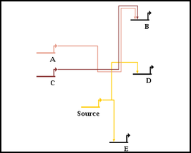
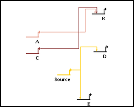
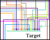
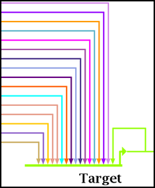
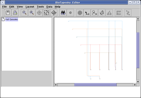
The automatic link-only layout algorithm (NOTE: NOT the whole-network layout template algorithms) only makes a quick first-pass layout of the links. Once you have run the link layout step, things are almost always improved by running one or more link optimization passes after the layout is complete. This is treated as a separate step, since it can take a very long time to complete with large networks. The optimization process tries to do things like eliminate link crossings, reduce link lengths and minimize link corners, as shown in the following before and after pictures:
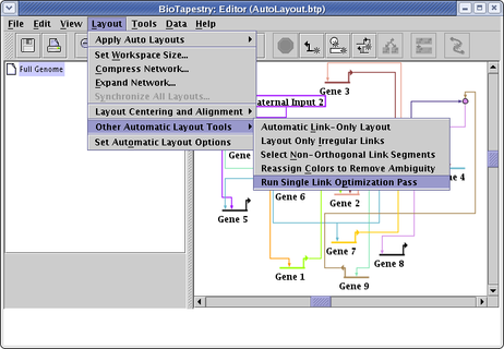
You can run an optimization of ALL the links in the layout by selecting Layout->Other Automatic Layout Tools->Run Single Link Optimization Pass from the main menu, as shown below. This is probably NOT what you want to do unless all the links in the network have been laid out by the link-only layout algorithm. In almost all cases, carefully laid out manual links will beat the automatic layout and optimization approach for clarity and simplicity! By running the optimization pass on manual links, or links laid out with the automatic full-network layout template algorithms, you will probably make things worse!
You can run any number of optimization passes as you want, though multiple passes usually converge on a final result after a few passes. The best way to track the changes is to cycle the Edit->Undo... and Edit->Redo... commands.
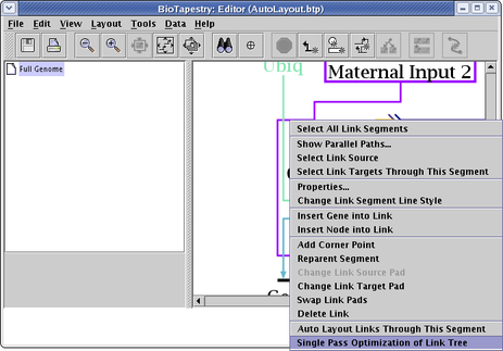
Probably the best approach to link optimizations is to focus on a single link tree by right-clicking on the tree and selecting Single Pass Optimization of Link Tree (see below). Note that the entire link tree is optimized, not just the links passing through the link segment you click on!
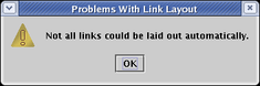
When you are using the automatic link layout tool (e.g. when running Layout->Other Automatic Layout Tools->Automatic Link-Only Layout or doing other tasks that use this feature), you may encounter this message and find that some links are left in an unorganized state:
With Version 3, the automatic link layout algorithm has been improved to deal with some of the cases which previously could not be handled. For example, it can now handle the case where you have two or more links landing on the same target pad, though the results will not be 100% orthogonal at the link terminus. (Note that the link layout algorithm does not change source or target pads; you need to do that manually.)
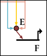
Probably the most common reason is that nodes are too close together, as shown below. Move the relevant nodes further apart, or expand the entire network before trying to apply the link layout step again. Having a large crowd of links around a node can also cause it to fail to find a path before it gives up.
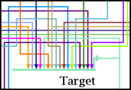
First, the automatic link-only layout feature is designed to come up with only a first-pass attempt at a link layout, and the result can have some undesirable anomalies. You can frequently improve things by running link optimization passes after the initial layout, as described in the section above. The link-only approach works tolerably for cases with relatively few inputs into a gene, but when the number of inputs gets large, the "bottom-up" approach used by the link-only algorithm just doesn't apply an effective strategy for coping with the crush of links:
Running a few passes of the optimizer can help, but the result still leaves something to be desired.
So while there are improvements planned for the link-only layout engine to handle many of its idiosyncrasies, the best approach to handling large numbers of inputs at the moment is to use the full layout template approach described above, which can do a better job:
There are several additional tools that can assist you in laying out a network:
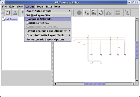
Network Compression and Expansion: After laying out a network, either manually or using the auto layout algorithms, you frequently have unused space that can be squeezed out to make the network more compact. Conversely, when you need to add new features, you often want to expand the layout first so you can fit the new items in. There are tools to do this compression and expansion for you. For compression, select Layout->Compress Network... from the main menu:
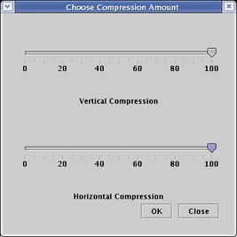
You can choose separate compression percentages for the vertical and horizontal directions:
The resulting network has had the extra space removed (though some padding always remains around each gene):
You can achieve roughly the opposite result by choosing Layout->Expand Network... from the main menu. You can repeat the expansion any number of times; the following shows the result of three 100% expansion steps:
Layout Synchronization: The layout of the top-level network is independent of the layouts used in the top-level instance submodels. Also, the layout of each top-level instance submodel is independent of all the others. Frequently, you wish to synchronize these independent layouts after making layout changes. Starting in Version 3, there is now a new tool that helps keep the top-level model layout in sync with other model layouts (see Layout->Propagate Layout to Full Genome Model...). It is frequently not obvious how to always do this automatically (i.e. if there are many second-level models with different layouts, and multiple regions in each model with unique layouts of different pieces of the top-level network, which do you want to use?). The tool helps you to specify a reusable strategy to use for this task.
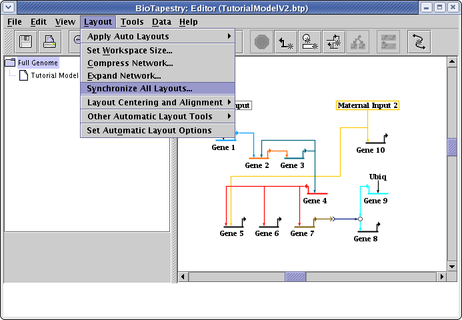
There is also a tool to synchronize layouts going in the other directon, propagating the top-level layout down to selected regions in selected submodels. (This fine-grained targeting of the synchronization is new in Version 3.) The top-level layout is duplicated (and optionally compressed) into each specified region of all the submodels, with a best effort approach to retain existing inter-region link layouts where applicable. In the special case where the submodels all have at most one instance of each network element in the top-level model, you can optionally make an exact duplicate of the top-level layout in the submodels. To use this feature, select Layout->Synchronize All Layouts... from the main menu.
Layout Centering and Alignment: There are some tools available to align and center your networks, which are available on the Layout->Layout Centering and Alignment submenu:
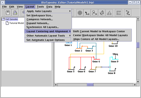
Shift Current Model to Workspace Center: You can draw a network anywhere in the available workspace, and this tool allows you to center it in the workspace whenever you want.
Center Workspace Under All Model Layouts: Once crucial aspect of laying out your various network models is now the layouts line up with each other as you shift between the various models. Sometimes, you want the networks to have their centers aligned. Other times, you want the networks to be offset from each other by certain amounts. If the latter is true, but you still want to shift all models at once by the same amount so that the set of all model layouts is (in the aggregate) centered in the workspace, this option will accomplish this.
Align Centers of all Model Layouts: This tool will try to line up all the various model layouts so that they lay on top of each other. You can choose to match the centers of the various layouts, or (if they various layouts share chunks of networks that are laid out exactly the same) you may get better results by specifying to overlay matching elements. This tool also lets you shift the resulting common center to the center of the workspace after the matching.
Select Non-Orthogonal Link Segments: When laying out links by hand, it's easy to get slightly crooked links (although if you hold down the Shift key while drawing a link, the segments are forced to run orthogonally). An intended future enhancement of BioTapestry is to have a link cleanup feature that just tweaks a link tree to make it orthogonal while maintaining the overall layout. In the meantime, there is a feature that will find and select all the non-orthogonal link segments, which then allows you to easily spot and fix any offending links. From the main menu, select Layout->Other Automatic Layout Tools->Select Non-Orthogonal Link Segments:
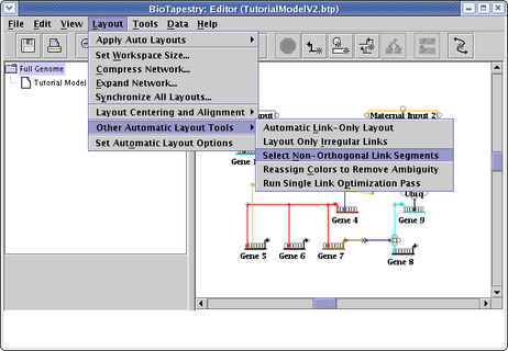
which will select the crooked segments, and zoom the display to enclose those selections. (Of course, if there are multiple widely-spaced crooked segments, zooming to just those segments may still give you a wide view of the network.)
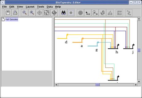
Reassign Colors to Remove Ambiguity: There are a wide variety of colors available for drawing nodes and their associated links, so that link crossings can be made unambiguous by insuring that all link crossings use different colors. A tool is available to do this color assignment, though for very large networks it may fail to do the whole job if there may not be enough colors to work with. To use this tool, select Layout->Other Automatic Layout Tools->Reassign Colors to Remove Ambiguity from the main menu:
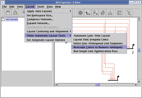
Which changes this example of identically colored source genes and links into an unambiguous coloring:
The layout can be propagated upward to the top-level model layout using a tool available by selecting Layout->Propagate Layout to Full Genome Model...; see the discussion above. The ability to just copy the layout "sideways" to some or all of another sibling submodel is on the list of requested enhancements. In the interim, you can partially achive this goal by propagating the layout up to the top-level model and then selecting Layout->Synchronize All Layouts... to push the layout back down to selected regions in selected submodels.