|
|
|
|
|
|
|
|
Note: This version of FAQ Answers: Simulation shows reduced-size screen shots. You can click on any image and see the full-size image in a separate window. To get the version with full-size images, go here.
The current version of BioTapestry has a very basic ability to do network simulations. Gene regulation is modeled using the framework described in the paper:
Bolouri, H. and Davidson, E. H. Transcriptional regulatory cascades in development: Initial rates, not steady state, determine network kinetics. Proc. Natl. Acad. Sci. USA 100, 9371-9376, 2003.
which is available here.
Here are some guidelines and limitations for the simulation feature:
![]() Only the top-level Full Genome model can be simulated; running
simulations of submodels is not yet supported.
Only the top-level Full Genome model can be simulated; running
simulations of submodels is not yet supported.
![]() The cis-regulatory occupancy requirements for a gene to function
can only be assigned as an AND, OR, or XOR of all the inputs.
The cis-regulatory occupancy requirements for a gene to function
can only be assigned as an AND, OR, or XOR of all the inputs.
![]() While custom installations of BioTapestry from source code can be
set up to run the ISB Dizzy Simulator directly within
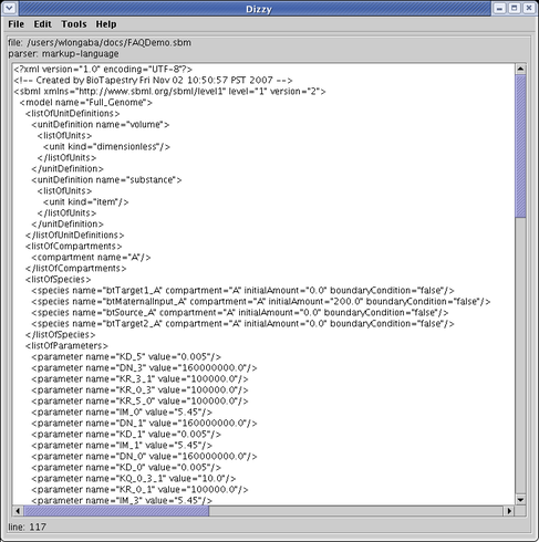
BioTapestry, the current generally available method exports an SBML file that is run
in a separate simulation program.
While custom installations of BioTapestry from source code can be
set up to run the ISB Dizzy Simulator directly within
BioTapestry, the current generally available method exports an SBML file that is run
in a separate simulation program.
![]() All links must have positive or negative sign. If this is not
the case, the File->Export->Export to SBML function is not available.
All links must have positive or negative sign. If this is not
the case, the File->Export->Export to SBML function is not available.
![]() If a non-gene node has no inputs, then it needs an assigned initial
value (initVal) and degradation constant (KD). If it has inputs, then it needs to be assigned to be an
arithmetic AND, OR, and XOR of its inputs, and also have an initial value (initVal) and an amplification
parameter (Kmult) assigned.
If a non-gene node has no inputs, then it needs an assigned initial
value (initVal) and degradation constant (KD). If it has inputs, then it needs to be assigned to be an
arithmetic AND, OR, and XOR of its inputs, and also have an initial value (initVal) and an amplification
parameter (Kmult) assigned.
![]() Don't include whitespace in the node and gene names, since this creates
a problem with parsing the SBML file.
Don't include whitespace in the node and gene names, since this creates
a problem with parsing the SBML file.
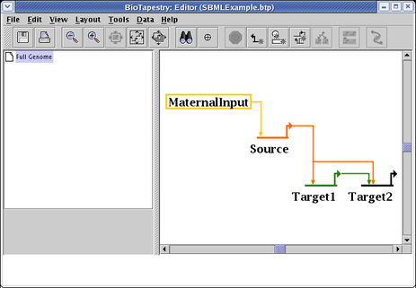
A short example how to run a simulation will use this simple model:
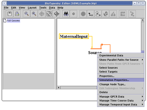
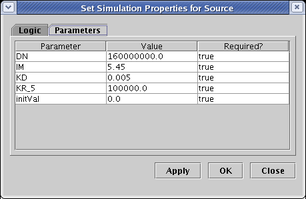
To set the simulation parameters for the various genes and nodes, right-click on the node and select Simulation Properties... from the pop-up menu:
On the Logic tab (not shown), you set the Logical Function applied to the inputs. On the Parameters tab (shown below), you need to set the various simulation parameters. See the paper for more information on these parameters. Unfortunately, the relative equilibrium constants (KR) and coefficients of cooperativity (KQ) for the various inputs are tagged with internal nodeIDs, so they can be hard to tell apart. The relationships can be found by studying the SBML output, but this needs to be fixed:
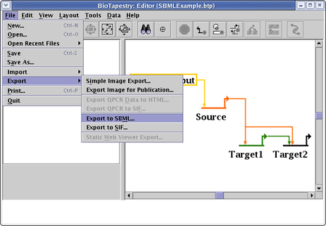
You then select File->Export->Export to SBML from the main menu, and create the SBML file:
Running the ISB Dizzy Simulator, you can load and view the exported SBML file:
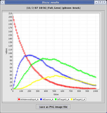
Finally, after running the simulation, you can see the results plotted up: